Filtration Efficiency and Particle Retention Rates of Pleated Filter Cartridges in Microelectronics
Abstract
In the rapidly advancing field of microelectronics, the demand for ultrapure water and highly controlled chemical environments is critical to ensure reliable semiconductor fabrication and device performance. Even submicron particles can cause defects in integrated circuits, significantly reducing product yield. Filtration technologies, particularly pleated filter cartridges, have become indispensable in achieving stringent purity requirements. This paper explores the filtration efficiency and particle retention rates of pleated filter cartridges within microelectronics manufacturing processes. The study examines the mechanisms of particle capture, structural characteristics of pleated filters, and their role in ultrapure water systems, photoresist filtration, and etching chemical processing. Emphasis is placed on the correlation between filter design parameters—such as pore size, pleat density, and membrane material—and their impact on retention efficiency and consistency in microelectronics applications.
1. Introduction
The microelectronics industry relies heavily on process consistency and contamination control. As semiconductor device geometries shrink below 5 nm nodes, the tolerance for contamination by submicron particles has dramatically decreased. Even particles as small as 30 nm can cause circuit failure or yield reduction. Consequently, maintaining ultrapure water (UPW) and high-purity process chemicals is one of the most crucial requirements in modern fabrication plants (fabs).
Pleated filter cartridges are widely used due to their high surface area, mechanical strength, and consistent retention characteristics. Unlike depth filters, pleated filters offer a balance between low pressure drop and high particle retention efficiency, making them particularly suitable for demanding microelectronics processes. This paper investigates the performance of pleated filters in terms of filtration efficiency and particle retention rates, two parameters that directly determine the reliability of contamination control in semiconductor manufacturing.
2. Importance of Filtration in Microelectronics
2.1 Ultrapure Water (UPW) Systems
UPW is the most extensively used material in semiconductor manufacturing. For every 1,000 liters of UPW consumed, even the presence of a few nanoparticles can introduce fatal defects. Pleated Membrane filter cartridges with sub-0.1 µm retention ratings are therefore essential at the point of use, ensuring that water delivered to wafers is free from both particles and microbial contaminants.
2.2 Photoresist and Chemical Processing
Photoresists are extremely sensitive to particle contamination, which may lead to lithography pattern defects. Similarly, etching and cleaning chemicals require high-purity conditions, as contaminants can alter chemical reactions and produce micro-defects on wafers. Pleated filters, particularly those made from PTFE, PVDF, or Nylon membranes, are optimized for chemical compatibility and particle removal efficiency in these environments.
2.3 Gas Filtration
While liquids are the primary concern, gases used in deposition and etching must also meet stringent purity standards. Pleated membrane filter cartridges designed for gas applications play a role in retaining particulates without restricting flow.
3. Mechanisms of Particle Retention in Pleated Membrane Filter Cartridges
The retention of particles in pleated filters occurs through multiple mechanisms, which include:
Sieving (Size Exclusion): The most direct mechanism, where particles larger than the pore size are trapped on the filter surface.
Adsorption: Electrostatic interactions between the filter media and charged particles can enhance retention.
Diffusion: Nanoparticles undergoing Brownian motion are captured by filter fibers.
Interception and Impaction: Larger particles following fluid streamlines collide with filter fibers due to inertia.
Pleated membrane filter cartridges combine these mechanisms, making them capable of capturing a broad spectrum of particle sizes while maintaining a low differential pressure.
4. Structural Features of Pleated Filter Cartridges Relevant to Microelectronics
The structure of a pleated filter cartridge significantly influences its efficiency and retention characteristics.
Pleat Density and Geometry: A higher pleat density increases the effective filtration surface area, which enhances particle holding capacity and prolongs filter lifetime.
Membrane Materials: Common choices include PTFE, PVDF, Nylon, PES (polyethersulfone), and PP (polypropylene). Each material offers different balances of chemical resistance, hydrophobicity/hydrophilicity, and retention capabilities.
Pore Size Distribution: Uniform pore size ensures consistent retention, critical for sensitive microelectronics processes. Filters with a narrow pore size distribution demonstrate higher reliability in preventing particle breakthrough.
End Cap and Seal Design: Ensures leak-free operation, critical for contamination-sensitive applications.
5. Filtration Efficiency in Microelectronics Applications
Filtration efficiency is defined as the percentage of particles removed by the filter compared to the total number present in the feed. In semiconductor manufacturing, the efficiency requirements are exceptionally high, often requiring 99.999% removal of particles ≥0.05 µm.
Factors influencing efficiency include:
Filter Media Pore Size: Smaller pore sizes correlate with higher removal efficiency, but may increase differential pressure.
Flow Rate: Higher flow rates can reduce residence time, lowering particle capture. Optimizing flow is therefore critical.
Operating Conditions: Temperature, pressure, and chemical compatibility affect membrane integrity and long-term efficiency.
6. Particle Retention Rates and Integrity Testing
The retention rate indicates the probability that particles of a certain size will be captured by the filter. For pleated filter cartridges used in microelectronics, absolute-rated membranes are preferred over nominal-rated ones to guarantee consistent retention.
Integrity tests such as the bubble point test, diffusion test, and pressure hold test are routinely performed to confirm that filters meet specified retention requirements before use in fabs.
For example:
A 0.1 µm-rated pleated PTFE filter may retain over 99.9999% of 0.1 µm latex beads during validation testing.
Retention validation is often required by SEMI (Semiconductor Equipment and Materials International) standards to ensure compliance.
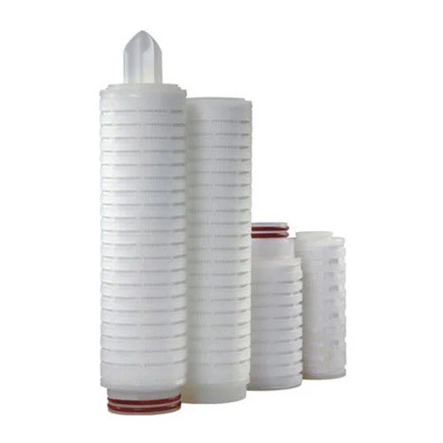
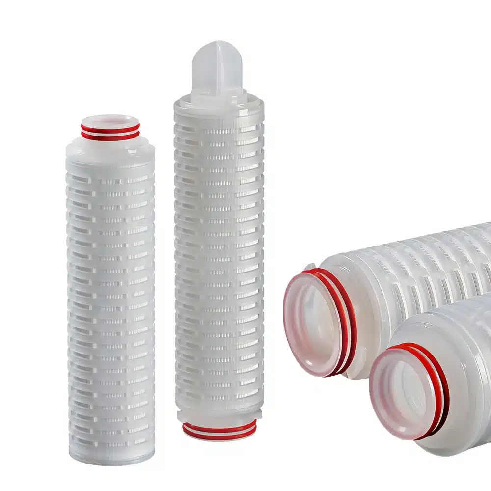
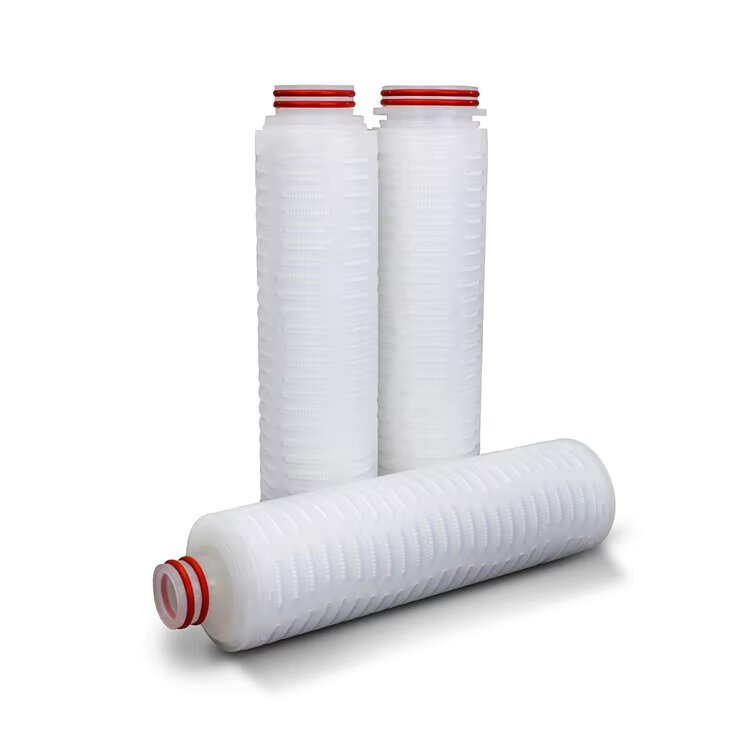
Recommended Filter Cartridges

7. Experimental Methods, Metrics, and Benchmarking
7.1 Test Fluids, Challenge Particles, and LRV
Filtration performance for microelectronics is typically characterized using monodisperse polystyrene latex (PSL) spheres or silica nanoparticles (e.g., 50–200 nm) suspended in UPW or relevant production chemicals (e.g., photoresist solvents or developers). The log reduction value (LRV) is widely used:
LRV=log10(CinCout)\text{LRV} = \log_{10}\left(\frac{C_{\text{in}}}{C_{\text{out}}}\right)LRV=log10(CoutCin)
where CinC_{\text{in}}Cin and CoutC_{\text{out}}Cout are the upstream and downstream particle concentrations. In practice, high-end pleated cartridges used at point-of-use (POU) on lithography tracks target LRV ≥ 3 at the rated pore size and can approach the instrument sensitivity limit (~LRV 5) for particles larger than the rating. Vendor validation frequently reports around LRV ≈ 3 at the rated size and higher as particle size increases, consistent with Entegris application data for 0.05 µm-rated “QuickChange” style filters.
7.2 Pore Size Rating and Integrity Testing
Absolute-rated membranes (PTFE, PES, PVDF, Nylon) are preferred over nominal ratings to assure consistency. Bubble point and diffusion/pressure-hold tests are standard qualification methods, correlating wetting characteristics and gas transport with the limiting pore size. In fluoropolymer membranes, pre-wetting using isopropanol (IPA) or low-surface-tension fluids is essential—especially for 0.05 µm PTFE—to avoid apparent low efficiency caused by incomplete wetting during validation.
7.3 Particle Counting and Analytical Windows
For UPW and dilute chemicals, online particle counters down to 0.05 µm are commonly leveraged near POU. Contemporary specifications informed by IRDS/ITRS and SEMI guidance target < 0.3 particles/mL @ 0.05 µm in advanced fabs; some guidance summarizes < 200 particles/L @ 0.05 µm as a practical threshold. These targets contextualize the required filter LRV and shed cleanliness of devices installed at POU.
8. Comparative Performance: Membrane Materials and Pleat Architecture
8.1 PTFE vs. PES vs. PVDF vs. Nylon
PTFE Filter Cartridge: Exceptional chemical resistance for aggressive solvents and developers; hydrophobic and requires pre-wet. Suitable for photoresist/solvent lines and resist strippers.
PES Filter Cartridge: Hydrophilic, low protein binding, widely used for UPW and aqueous chemicals; strong performance at 0.05–0.2 µm for particle retention with moderate ∆P. Product families (e.g., ProcessGard® PES) illustrate retention bands (0.04/0.05/0.1/0.2 µm) and sterilization envelopes for semiconductor/adjacent markets.
PVDF Filter Cartridge: Good balance of chemical resistance and hydrophilicity; popular in oxidizing chemistries and UPW POU.
Nylon Filter Cartridge: High mechanical strength and wettability; used in developer and post-CMP cleans where compatibility permits.
8.2 Pleat Density, Flow Distribution, and ∆P
Higher pleat density and optimized flow distributors (e.g., asymmetric support layers) increase effective area, improving holding capacity without proportionally raising differential pressure (∆P). However, overly tight pleat packs can elevate local face velocity and shear, reducing capture of diffusive nanoparticles. Empirically, best-in-class cartridges maintain LRV ≥ 3 at rated size over the usable life while keeping initial ∆P < 0.1–0.2 bar at design flow for 10-inch formats—numbers that align with supplier data sheets and application notes.
8.3 Device Shedding and Clean Build
At ultra-low upstream particle counts, filter self-cleanliness becomes limiting: devices must not contribute particles. Supplier validation commonly reports device cleanliness testing (rinsing to baseline before release). This is emphasized in chemical filtration application notes, which warn that in extremely clean fluids filter contribution can dominate measured downstream counts if devices are not properly conditioned.
9. Case Studies and “Latest Data” Context
9.1 UPW POU Filtration for Advanced Nodes (Lithography Track)
Fabs operating at leading nodes have tightened UPW particle specs guided by SEMI F63 and IRDS Yield Enhancement workstreams. Current guidance highlights that particles are the most critical contamination class for random yield loss; proactive particle control in UPW is therefore pivotal to achieving ≥ 80% yield at advanced nodes. POU ultrafiltration or 0.05–0.1 µm pleated cartridges are used redundantly to maintain ≤ 0.3 particles/mL @ 0.05 µm, with online counters at the track interface.
Observed outcome (industry-reported benchmarks): sustained sub-spec particle levels correlate with statistically significant reductions in lithography defectivity. IRDS YE 2023 reiterates that focus on particles provides the most leverage for random yield, reinforcing investment in POU filtration and monitoring.
9.2 Photoresist and Solvent Lines (Fluoropolymer Membranes)
On PR dispense and solvent flush lines, 0.05–0.1 µm PTFE pleated cartridges are common. Field validations show that a rigorously controlled pre-wet protocol for PTFE (IPA displacement followed by UPW or compatible solvent) eliminates microbubble-related counting artifacts and restores the expected LRV ≥ 3 at rated size, as documented by supplier guides. The result is improved line stability and fewer post-exposure inspection (PEI) particle defects.
9.3 Aqueous Chemical Cleans and Developers (PES/PVDF)
Where chemistry allows, hydrophilic PES or PVDF pleated membranes at 0.05–0.2 µm deliver robust retention with lower ∆P. Commercial lines (e.g., ProcessGard® PES) publish sterilization and operating envelopes that ease integration in high-temperature loops and enable predictable end-of-life (EOL) behavior based on ∆P rise. In pilot deployments, swapping depth-only prefilters for asymmetric PES pleated at the POU can cut downstream 0.05–0.1 µm counts by > 1 LRV while holding total system ∆P constant.
9.4 CMP Post-Polish Clean Rinses
Post-CMP cleans are sensitive to sub-100 nm silica and polymeric fragments. Reports from UPW and tool-maker communities suggest that combining terminal ultrafiltration with pleated cartridges at the track feed consistently meets < 1 particle > 0.05 µm per mL near extraction points. This hybrid strategy mitigates transient spikes from loop disturbances and valve operations.
10. Interplay with Industry Specifications
10.1 SEMI Standards (F61, F63, F75)
SEMI F63 defines UPW quality and is used to set procurement and control criteria; F61 guides UPW system design; F75 addresses monitoring. Together, they frame filter performance targets within a complete UPW lifecycle from plant to POU.
10.2 IRDS/ITRS Yield Enhancement
The IRDS Yield Enhancement chapters (2022–2023) underscore that particle control outranks other contamination classes for random yield, and provide quantitative relationships between allowed defect density and killer particle sizes for an 80% minimum yield target—context that justifies aggressive filtration and monitoring at POU.
10.3 Metals, Ions, and Molecular Impurities
While this paper focuses on particulates, practical programs must co-optimize particle removal with trace metals/ions (ppt level) that are governed by ASTM D5127 and SEMI F63; recent method compendia (ICP-MS/ICP-QQQ) demonstrate sub-ppt detection consistent with these standards.
11. Lifecycle and Cost-of-Ownership (CoO) Considerations
11.1 Selecting the “Right-Sized” Rating
Undersizing (e.g., deploying 0.05 µm when 0.1 µm suffices) inflates ∆P, shortens life, and may add risk of gas nucleation in high-purity solvents; oversizing compromises retention. A data-driven approach—linking upstream particle spectra, LRV curves, and target defect density—is recommended.
11.2 Managing ∆P and Throughput
For a fixed target LRV, trading pleat density and area against face velocity can cut initial ∆P by 20–40% without sacrificing capture efficiency, provided flow distribution remains uniform. Vendor A/B trials commonly document stable LRV with lower ∆P when moving to asymmetric membrane + higher area designs.
11.3 Device Cleanliness and Pre-Conditioning
Proper pre-flush to steady-state particle baseline is mandatory in UPW and dilute chemistries. Without it, downstream counters may reflect device contribution rather than process contamination, potentially masking true performance.
12. Future Directions
Sub-50 nm Capture Modeling: As feature sizes shrink, Brownian diffusion and electrostatic interactions dominate. Advanced CFD + stochastic models for pleat channels will refine predictive LRV at ultra-low face velocities.
Hybrid Modules (UF + Pleated): Integrated housings that co-package terminal ultrafiltration with pleated POU stages to stabilize < 0.05 µm counts during flow transients.
Real-Time Integrity Sensing: Correlating micro-flow gas diffusion signals with LRV drift to trigger predictive maintenance before ∆P limits are reached.
Ultra-Clean Constructions: Even lower shedding via clean-build-to-spec (CBTS) assembly, fluoropolymer internals, and low-extractable adhesives to meet emerging UPW particle targets.
13. Conclusions
Pleated filter cartridges remain a cornerstone of contamination control in microelectronics. When rating selection, pleat architecture, and device cleanliness are aligned with SEMI F63/F61 and IRDS yield guidance, cartridges can reliably deliver LRV ≥ 3 at the rated size, maintain sub-spec 0.05 µm particle counts at POU, and support stable high-yield manufacturing. For photoresist and solvent services, PTFE pleated membranes—correctly pre-wetted—provide the needed retention without compromising chemical integrity. For UPW and aqueous cleans, PES/PVDF pleated options balance low ∆P with high retention. Integrating terminal ultrafiltration with pleated POU stages and adopting proactive monitoring closes the loop between specification and on-tool reality, directly supporting the yield targets outlined by the IRDS.
References
SEMI F61 – Guide to Design and Operation of a Semiconductor Ultrapure Water System. SEMI Store. semi.org
SEMI F61 (public draft excerpt / guide update) – SEMI download (background and objectives).
SEMI F61 (mirrored PDF excerpt) – Antpedia mirror (engineering and component requirements).
SEMI F63 – Guidelines for Ultrapure Water Used in Semiconductor Processing (references and summaries). balazs.com
IRDS Yield Enhancement 2022 – The International Roadmap for Devices and Systems (Yield Enhancement).
IRDS Yield Enhancement 2023 – Yield Enhancement with Reliability as a Driver for Contamination Control.
IRDS White Paper 2023 – Proactive Particle Control in UPW (killer particle size vs. yield).
Entegris Application Note – Chemical Filtration: Designing for Overall Equipment Effectiveness (LRV at 0.05 µm; device cleanliness).
Entegris Datasheet – Microgard™ Liquid Filters (retention codes incl. 0.05 µm).
Entegris Product Page – ProcessGard® PES/PP/PS Filters (retention ratings and operating envelopes).
Pall Guide (Fluoropolymer Filters) – PTFE pre-wetting recommendations (0.05 µm).
Agilent ICP-MS/QQQ – UPW metals detection consistent with SEMI F63 & ASTM D5127 (sub-ppt DL/BEC).
Hach (Semiconductor Water Applications) – POU ultrafiltration to < 1 particle > 0.05 µm per mL near extraction points.
UPW Overview (encyclopedic) – Practical spec summary including < 200 particles/L @ 0.05 µm and process context.